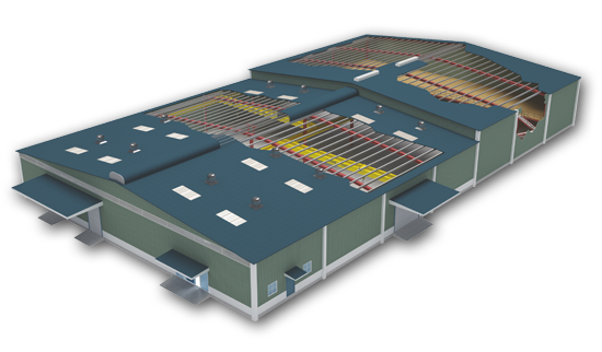
The Pre-Engineered Building’s (PEB) is based on the concept specially known for its structural strength, economical design and its compactness. Pre-engineered Buildings outclass the traditional concept of construction. PEB system comprises primary, secondary structures, roofing, cladding & accessories which are designed as per Indian & international standards. Fabrication of these structures involves Technology- led & qualitative manufacturing methods used at the factory that can efficiently satisfy a wide range of structural and aesthetic design requirements according to the dimensions for easy handling and assembling process executed at site.
A Quick Glimpse on Pre-Engineered Building System & Its Advantages & Application
The Pre-Engineered Building’s (PEB) is based on the concept specially known for its structural strength, economical design and its compactness. Pre-engineered Buildings outclass the traditional concept of construction. PEB system comprises primary, secondary structures, roofing, cladding & accessories which are designed as per Indian & international standards. Fabrication of these structures involves Technology- led & qualitative manufacturing methods used at the factory that can efficiently satisfy a wide range of structural and aesthetic design requirements according to the dimensions for easy handling and assembling process executed at site.
ADVANTAGES OF PEB
APPLICATION:
The basic parameters that define a pre-engineered building are: Building Width, Building Length, Building Height, Roof Slope, End bay length, Interior bay length and Design Loads
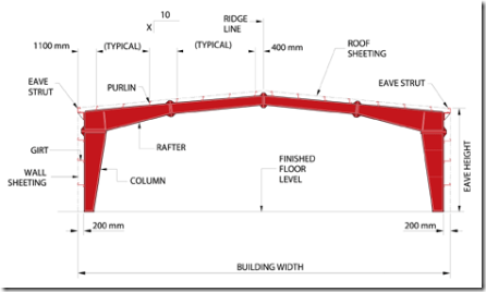
No matter what primary framing system is used, the building width is defined as the distance from outside of eave strut of one sidewall to outside of eave strut of the opposite sidewall. Building width does not include the width of Lean-To buildings or roof extensions.
The longitudinal length of the building measured from out to out of end wall steel lines.
This is the angle of the roof with respect to the horizontal. The most common roof slopes are 0.5/10 and 1/10. Any practical roof slope is possible.
Building height is the eave height which usually is the distance from the bottom of the main frame column base plate to the top outer point of the eave strut. When columns are recessed or elevated from finished floor, eave height is the distance from finished floor level to top of eave strut.
The distance from outside of the outer flange of endwall columns to center line of the first interior frame column.
The distance between the center lines of two adjacent interior main frame columns. The most common bay lengths are 6 m, 7.5 m and 9 m.
Unless otherwise specified Zamil Steel pre-engineered buildings are designed for the following minimum loads:
Roof Live Load: 0.57 kN/m2
Design Wind Speed: 110 km/h
Design for snow loads, earth quake loads, collateral loads, crane loads or any other loading condition, if required must be specified at the time of request for quotation.
Loads are applied in accordance with the latest American codes and standards applicable to pre-engineered buildings unless otherwise requested at the time of request for quotation.
Design & Codes
PRE-ENGINEERED BUILDING
Unless otherwise specified, MSIPL Pre-Engineered Building is designed as per the MBMA standard. Design parameter of earthquake loads, collateral loads, crane loads or any other loads are any other loading conditions and local conditions must be specified when requesting a quotation. Loads are applied in accordance with American codes and standards applicable to pre-engineered building unless otherwise requested at the time of quotation.
Design as per MBMA:
The 2002 Edition of Low Rice Building System Manual of Metal Building Manufacture Association (MBMA).
All applicable loads are as per MBMA
Hot rolled and build up section are designed in accordance with:
Manual of Steel Construction, 9th Edition of American Institue of Steel Construction (AISI).
Cold – Formed members are designed in accordance with:
1996 Edition of Cold-Formed Steel Design Manual of American Iron and Steel Institute (AISI).
Welding is applied in accordance with:
Structural Steel Welding Code of American Welding Society (AWS.D1.98).
Design as per Indian Standard :
IS – 875 (Part I) – 1987 : Code of Practice for Design Dead Loads for Building and Structures.
IS – 875 (Part II) – 1987 : Code of Practice for Design Imposed Loads for Building and Structures.
IS – 875 (Part III) – 1987 : Code of Practice for Design Wind Loads for Building and Structures.
IS – 1893 (Part I) – 2002 : Criteria for Earthquake Resistance Design of Structures.
IS 2062 : 2006 – Steel for general structural purposes.
IS 808 : 1989 – Dimensions for hot rolled steel beams, columns, channels and angles.
Design of prismatic Hot rolled and built up section is in accordance with:
IS – 800 (1984 & 2007) : Code of Practice for General Construction in Steel.
Design of Tapered Built up section is in accordance with : Manual of Steel Construction, 9 th Edition of American Institute of Steel Construction (AISC).
Cold – Formed members are designed in accordance with:
IS – 801 (1975) : Code of Practice for use of Cold – Formed Light Gauge Steel Structure.
Welding is applied in accordance with : Structural Steel Welding code of American Welding Society (AWS D1.1.98)
IS – 816 (1969) : Code of Practice for use of Metal Arc Welding for general construction
© 2019 G.K. Fabrication All Right Reserved.Design & Developed by
 InnovTouch Technologies